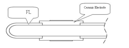
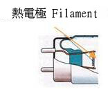
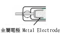
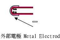
Technically, unlike the conventional FL with metallic electrodes, CPFL’s linearly polarized ceramic poles are welded directly to the fluorescent tube (Fig. 1). As a reference, Figs. 2 through 4 show the Hot-Cathode FL, Cold-Cathode FL, and External electrode FL technology, respectively.
Fig. 1 Ceramic Electrodes joining with the FL |
|
Comparison between CPFL and other Metallic-Electrode FLs.
The CPFL disruptive technology has the following merits over the conventional ones in the following aspects:
![]() 1. No high kickoff voltage needed
1. No high kickoff voltage needed
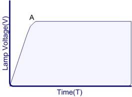
CPFL utilizes the strong electric field, once powered, forming around the ceramic poles to ionize the mercury gas in the evacuated FL tube. The formation of ionized gas, or plasma, has no need for high kickoff voltage (Fig. 5.).
Fig. 5. CPFL Starting Voltage Vs. Time
![]() 2. Negligible decay in luminosity
2. Negligible decay in luminosity
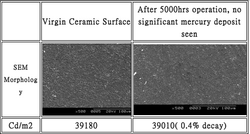
Ceramic electrodes do not form amalgam at high temperature, nor do they oxidize; hence the optical decay is comparatively slow. As a result, less mercury vapor is needed to fill the lamp (only about 1.6 mg-5mg) and the less decay in luminosity with time is resulted. This is shown in Table 1; after 5,000 hours of operation, the SEM shows zilch mercury deposit on the ceramic electrodes, and almost no detectable decay in luminosity.
Table 1 CPFL Luminosity Decay before and after 5,000 hrs’ operation
![]() 3. Parallel Operation
3. Parallel Operation
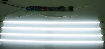
No need for kickoff voltage, more than one FL can operate in parallel (Fig . 6) with a single inverter. This results in cost savings in wiring and system control.
Fig 6. CPF wired In Parallel
![]() 4. Linear I-V curve Characteristics
4. Linear I-V curve Characteristics
CPFL’s characteristic positive near-linear I-V curve facilitates adjustable (0-100%) optical output without sacrificing the lamp life, as shown in Fig 7.
Fig 7. CPFL I-V Curve
![]() 5. Steady luminosity from steady Dielectric constant of CPFL
5. Steady luminosity from steady Dielectric constant of CPFL
As shown in Fig. 8, CPFL dielectric constant remains almost constant over a wide temperature range ( -40℃ to 250℃). Hence a steady electrical field is maintained, and so is the luminosity.
Fig 8. CPF Dielectric Constant Vs. Temperature
![]() 6. Linear Polarization
6. Linear Polarization
Ceramic materials tend to polarized readily (Fig. 9) and this results in less current loss, and hence less energy waste.
Fig. 9 CPF polarization vs. Electrical Field
![]() 7. Tight vacuum seal ensuring long life operation
7. Tight vacuum seal ensuring long life operation
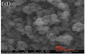
The high-density nano-ceramic structure of core shell, shown in Fig. 10, guaranteed a tight vacuum seal for the lamp. This has to do with the ceramic thermal expansion coefficient is close to that of glass.
Fig. 10 Magnified CPFL core shell
![]() 8. Differential temperature gradient enhancing energy conversion efficiency
8. Differential temperature gradient enhancing energy conversion efficiency
As shown in Fig. 11, the lamp surface temperature of a CPFL is comparatively low. Once powered, the electric field near the wall is high while the internal of the lamp is lower and is conducive to ion recombination; hence more heat is released:
(Ar+ + Ne+ + Hg+)+ e- → Ar、Ne、Hg + Q(heat)
The resulting heat Q is important in visible light conversion at low environmental temperature. Likewise, the intense electric field near the wall results in smaller probability of recombination and hence low tube temperature.
Fig. 11 CPFL Electrical Field Density Diagram